

Views: 0 Author: Site Editor Publish Time: 2026-06-19 Origin: Site


Selecting the wrong industrial or commercial cooling solution isn't just an efficiency issue—it’s a systemic risk. Placing a high-volume fan in a high-resistance system can lead to motor failure, aerodynamic stalling, and excessive downtime. Engineers and facility managers constantly face ventilation challenges requiring precise pressure and flow dynamics.
While both fan types move air to regulate temperature and exhaust particulates, their mechanical design dictates entirely different performance curves. Mismatching the blower type to your static pressure needs guarantees poor performance and accelerates equipment degradation.
This guide unpacks the mechanical differences, engineering limits, and critical failure risks of centrifugal and axial configurations to help you specify the exact component for your application. You will learn how to map working points, identify stall regions, and deploy the correct aerodynamic profile for your specific project constraints.
Direction of Flow: Axial fans pull air parallel to the shaft (straight through); centrifugal fans draw air into the center and expel it at a 90-degree angle (radial).
Volume vs. Pressure: Axial configurations deliver high volumetric flow (CFM) at low pressure. Centrifugal fans deliver lower relative volumes but excel at overcoming high static pressure.
The Golden Rule of Resistance: If your system relies on complex ductwork, filters, or dampers, a centrifugal fan is required. For open-air, non-ducted applications, axial is the standard.
Catastrophic Risks: Operating an axial fan in a high-resistance environment causes "stalling," while running a forward-curved centrifugal fan in a zero-resistance space can cause rapid motor burnout.
Before diving into specific aerodynamic differences, we must understand the baseline mechanics unifying these devices. They operate on shared physical principles.
Both types rely heavily on electric motors for propulsion. Manufacturers build them using either Alternating Current (AC) or Direct Current (DC) motor types. You will find both designs highly scalable. They cool small desktop computers, and they ventilate massive subterranean mining networks. Fundamentally, they manipulate fluid dynamics. They transfer thermal energy away from sensitive components. They also transport airborne particulates out of hazardous workspaces.
Engineers cannot evaluate performance by looking at physical dimensions alone. Performance evaluation requires identifying a specific "working point" on a fan performance curve. You must balance the volumetric flow rate against the system's static pressure. In metric units, we measure flow in cubic meters per hour ($m^3/h$). In imperial units, we use cubic feet per minute (CFM). We measure static pressure in Pascals (Pa) or inches of water gauge (inWG). A large fan operating at the wrong working point will underperform a smaller, properly specified unit.
Both fan categories support two primary motor configurations: direct-drive and belt-drive. Direct-drive setups mount the impeller directly to the motor shaft. This creates a compact footprint. It also significantly lowers maintenance requirements because there are no belts to tension or replace. Belt-drive setups separate the motor from the impeller using pulleys and belts. We use belt-drive configurations when we must isolate the motor from hazardous, corrosive, or extremely hot airflows.
The core distinction between these two systems lies in how they direct air and handle resistance. The specific blade geometry defines their aerodynamic limits.
Axial designs operate much like airplane propellers. They excel at moving massive amounts of air quickly.
Airflow Path: The propeller-like design pushes air straight through the axis of rotation. Air enters parallel to the shaft and exits in the exact same parallel direction.
Performance Limits: They handle maximum static pressures up to roughly 5,000 Pa. However, they are capable of massive airflows. Heavy industrial setups can push up to 830,000 $m^3/h$.
Efficiency & Footprint: They remain highly energy-efficient for open spaces. The inline nature of the airflow allows for an incredibly compact and lightweight physical design.
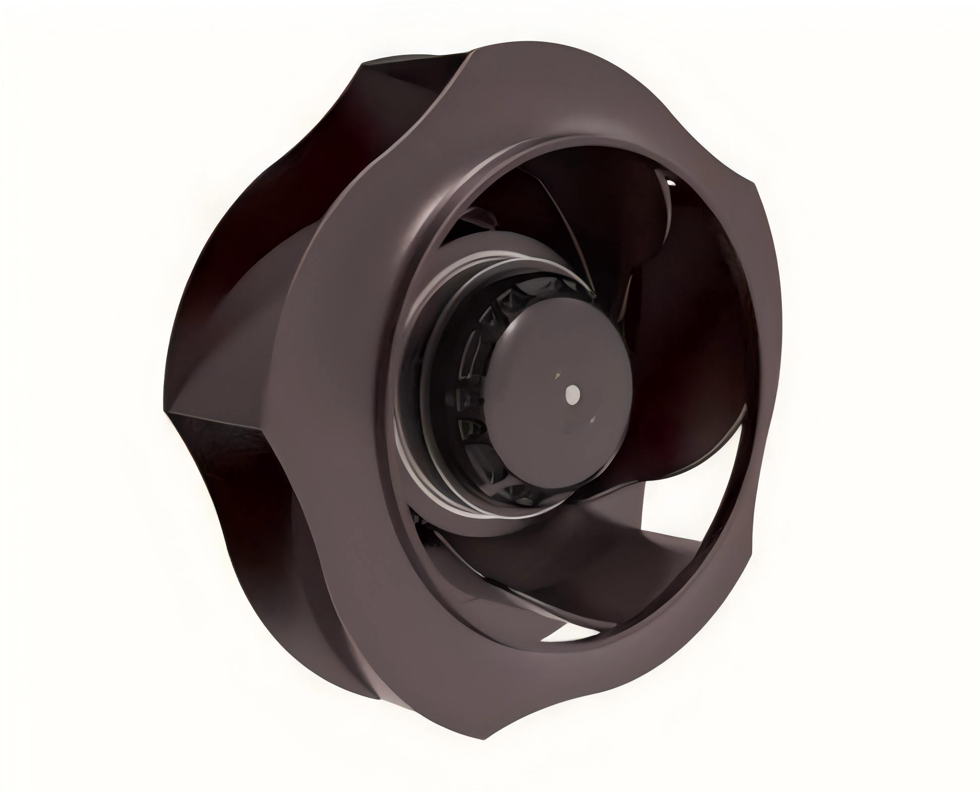
A centrifugal fan generates pressure through centrifugal force. It functions as a heavy-duty motorized impeller.
Airflow Path: The device functions as a blower. The rotational force pushes air outward toward the housing edge. It then expels the air perpendicularly (at a 90-degree angle) from the intake.
Performance Limits: Engineers design these units for high resistance. Heavy-duty industrial models easily overcome extreme static pressures up to 25,000 Pa.
Blade Variations: Output performance depends heavily on the specific blade geometry. Backward-curved blades offer high speed and peak efficiency. Forward-curved blades deliver moderate output with lower acoustic noise. Inline configurations exist to combine radial pressure generation inside a straight tubular housing.
Specification Feature | Axial Configuration | Centrifugal Configuration |
|---|---|---|
Airflow Path | Straight-through (Parallel) | 90-degree deflection (Radial) |
Max Volumetric Flow | Up to 830,000 $m^3/h$ | Generally lower per unit size |
Max Static Pressure | Up to 5,000 Pa | Up to 25,000 Pa |
Primary Strength | High volume, open space | Overcoming severe duct resistance |
Misapplying fluid dynamic equipment leads to catastrophic mechanical failures. You must understand the specific failure modes of each design to ensure system reliability.
Axial configurations possess a specific aerodynamic vulnerability when facing heavy resistance.
The Risk: Pushing an axial unit against high back-pressure pushes the operation directly into the stalling region. High back-pressure commonly stems from dense HEPA filters, long winding pipes, or partially closed dampers.
The Outcome: The aerodynamic lift on the blades entirely collapses. The fluid detaches from the blade surface. This causes severe mechanical vibration and sharp noise spikes. You will see an immediate, drastic drop in cooling efficiency. The motor will continue to spin, but little to no air will actually move through the system.
Best Practice: Always consult the manufacturer's performance curve. Ensure your calculated system resistance falls well below the documented stall dip on the graph.
Certain radial designs hide an electrical risk linked to pressure drops.
The Risk: Forward-curved blowers feature a rising horsepower curve. They actually rely on system back-pressure to limit the motor's electrical workload. Resistance acts as a physical brake on the impeller.
The Outcome: If you place this specific blower in an open, non-ducted environment with zero resistance, disaster strikes. The fan attempts to move too much air. It over-amps the circuit. It will rapidly burn out the motor windings due to extreme heat generation.
Common Mistake: Technicians often remove ductwork for testing and run the blower in open air. This action instantly overloads the motor. Always test forward-curved units with their attached ductwork or use an artificial dampener to simulate resistance.
System designers choose components based on environmental constraints. Open spaces demand one approach, while enclosed systems demand another.
You should choose axial models when you need to move vast amounts of air without fighting tight channels.
Electronics & IT: Heat exchangers, server racks, and localized PCB (Printed Circuit Board) cooling rely on these compact units. They provide immediate, high-volume airflow across hot internal heat sinks.
General Ventilation: We use massive axial units for tunnel ventilation, cooling towers, and commercial condenser fans. They sweep large open areas efficiently.
Consumer/Medical: Medical ventilators use highly precise axial designs. We also see them in localized exhaust systems where tight space and low initial capital costs are top priorities.
You must specify a heavy-duty centrifugal fan whenever air must travel through restrictive pathways.
Harsh & Abrasive Environments: Systems handling dense dust, corrosive chemicals, or high-temperature gases require radial designs. Engineers often utilize belt-drive setups here to protect the motor entirely from the abrasive airstream.
HVAC & Industrial Processes: Pneumatic material conveying relies on high pressure to push solid materials through pipes. We also use them for filter flushing, gas boosting, and driving air through complex multi-story HVAC ductwork.
Specialized Enclosures: Solar inverters pack tight electronics into small spaces. These applications require the highest airflow performance per volume of space. Custom housings direct the radial airflow precisely over critical hot spots.
Use these specific criteria to finalize your procurement specifications. Proper evaluation prevents costly retrofits.
Acoustics matter in commercial spaces. Centrifugal units generally produce more noise. This happens due to the higher operating pressures and the violent 90-degree directional shift of the air inside the housing. If noise is a hard constraint, you must design extensive sound attenuation into your ductwork. Furthermore, DC axial units typically generate the lowest electromagnetic interference (EMI). They are ideal for sensitive telecommunications and medical imagery equipment.
Physical footprint dictates many engineering choices. Axial designs fit tight, linear spaces perfectly. You can mount them directly into walls or shallow panels. Centrifugal units require distinct scroll-shaped housing designs. They need physical space to direct the radial airflow properly. You cannot easily flatten them without compromising their pressure-generating capabilities.
Industrial environments pose severe chemical and thermal challenges. Does the environment require ATEX (explosion-proof) certification? Do you need acid-resistant coatings like ECTFE or PP? Does the application involve extreme heat tolerance, sometimes up to 700°C? Radial designs typically offer much broader customization for these heavy-duty executions. Manufacturers cast their robust housings from specialized alloys more readily than lightweight axial frames.
Energy consumption profiles differ drastically. Axial models represent lower initial capital investment. They also feature much lower power consumption when operating in free-air. Centrifugal systems require higher upfront investment. They pull more power under heavy loads. However, they remain absolutely non-negotiable for overcoming system resistance. Trying to save power by installing an axial unit into a ducted system will simply result in stall conditions and zero airflow.
Calculate total static pressure drop across all filters and ducts.
Verify available physical mounting space (linear vs. 90-degree).
Determine maximum acceptable acoustic levels (dBA).
Identify necessary chemical or thermal resistance certifications.
Ensure the working point avoids the aerodynamic stall region.
The choice between axial and centrifugal designs is rarely a matter of personal preference. System resistance and required static pressure strictly dictate your selection. Open air requires axial flow; complex ductwork demands radial force.
We recommend auditing your system’s total pressure drop before reviewing CFM requirements. Choose axial units for raw volume and efficiency in open configurations. Select a radial unit for reliability and pressure in constrained, resistant systems.
As a final next step, always consult with a thermal engineer. Utilize professional fan-curve simulation software to map your specific working points accurately before finalizing your Bill of Materials (BOM). Precision in the planning stage eliminates catastrophic failures in the field.
A: Vacuum cleaners require immense "pull" to overcome the resistance of thick carpet, dense dirt, and layered filters. High static pressure makes the centrifugal design the only viable choice. Leaf blowers require maximum "push" volume (high CFM) in an open-air environment. This perfectly aligns with axial capabilities, maximizing airflow velocity over a wide area.
A: Because air is a compressible fluid, the volumetric flow rate (CFM) can slightly change when passing through a massive high-pressure differential. However, according to strict fluid dynamics principles, the mass flow rate remains conserved. The exact same mass of air enters the inlet and exits the outlet.
A: Yes. A larger fan operating at a significantly lower RPM can achieve the exact same volumetric flow (CFM) as a smaller fan running at a high RPM. Moving the same air at a lower rotational speed typically results in significantly lower acoustic noise and reduced mechanical vibration.


