

Views: 0 Author: Site Editor Publish Time: 2026-06-10 Origin: Site


Industrial processes and commercial HVAC systems depend heavily on precise airflow management. If you choose the wrong equipment, you risk catastrophic system inefficiencies. Poor choices also lead to excessive acoustic noise and premature motor failure. Axial units usually handle basic cooling tasks perfectly well. However, high-resistance environments demand a much more robust approach. Facilities pushing air through complex ductwork need equipment built for strict aerodynamic demands.
This guide clarifies the fundamental mechanical principles behind every centrifugal fan. We will break down the differences between core blade designs. This ensures you understand how geometry impacts performance. You will also learn an evidence-based framework for specifying the right hardware. By the end, you will confidently select equipment tailored for high-pressure, directional airflow applications.
Centrifugal fans (or blowers) accelerate air radially, changing its direction by 90 degrees to produce a high-pressure, highly directional air stream.
Blade geometry—forward-curved, backward-curved, or straight radial—dictates the fan's efficiency, acoustic profile, and ability to handle airborne particulates.
Unlike axial fans, centrifugal units require rigid mounting infrastructure due to their heavier volute casings and higher power input requirements.
Common implementation failures stem from miscalculating static pressure limits (causing backflow) or incorrect wiring (causing hard-to-diagnose low-output operation).
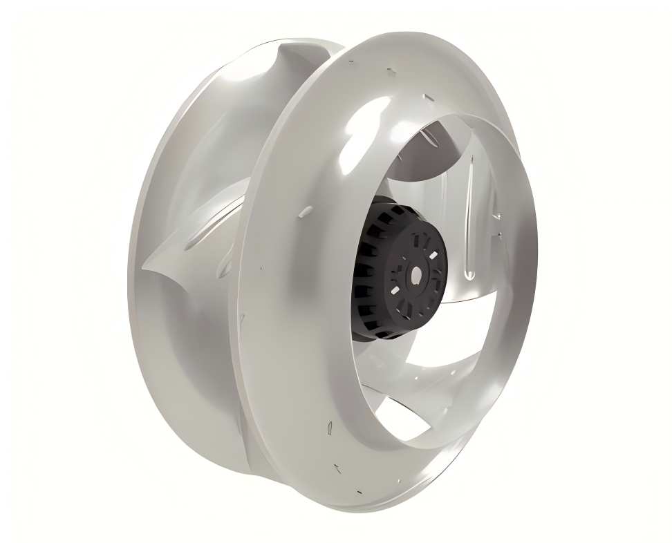
Airflow generation relies on precise mechanical geometry. A standard unit features a motor that drives a central impeller. This impeller sits inside a volute casing. Engineers often shape this casing like an ammonite shell. The rotating impeller draws air directly into its central hub. Centrifugal force then throws this air outward. Finally, the volute casing guides the expelled air perpendicularly away from the intake.
Many professionals use the terms interchangeably. However, strict engineering standards separate them. The American Society of Mechanical Engineers (ASME) defines a clear technical boundary. They base this boundary on the pressure ratio. This is the discharge pressure divided by the suction pressure. A true fan operates at a pressure ratio up to 1.11. Blowers operate at higher ratios between 1.11 and 1.20. Compressors handle ratios above 1.20.
You must understand the constant volume principle. A centrifugal fan is a constant-volume device. It moves a consistent volume of air at any set rotational speed. However, the actual mass of that air fluctuates. Environmental changes affect air density. Temperature spikes or altitude drops change how much mass the unit moves. You must account for density when calculating real-world performance.
Peak pressure generation is an engineering reality. It relies entirely on tight manufacturing tolerances. The physical gap between the spinning blades and the stationary housing matters deeply. Proper blade-to-housing clearances sit around 0.25% of the total impeller diameter. If you increase this gap, air leaks backwards. This leakage destroys static pressure and ruins system efficiency.
Impeller geometry dictates how a system handles air. You cannot swap blade types without changing system dynamics. We evaluate three primary configurations below.
These blades curve in the direction of the fan wheel's rotation. They scoop the air forward as they spin.
Outcomes: This design yields a significantly lower noise profile. It also allows for a compact footprint.
Limitations: They are highly sensitive to airborne particulates. You must strictly limit them to clean-air applications. Electrical control is often managed via simple motor current monitoring.
These blades curve against the direction of rotation. They sweep backward away from the spinning motion.
Outcomes: They deliver the highest energy efficiency available. They also generate massive static pressure. They can easily handle light dust and moisture.
Implementation: Manufacturers often design them as housing-less "plug fans." You cannot control them by motor current alone. They require active pressure-differential measurement at the nozzle.
These blades extend straight out from the center hub. They look like a simple paddle wheel.
Outcomes: They produce extremely high pressure at lower overall volumes. The flat design prevents solid material accumulation. We call this a self-cleaning feature.
Use Cases: They are ideal for harsh industrial environments. You will see them in pneumatic conveying systems and heavy particulate control. However, they generate the highest acoustic noise.
Impeller Selection Chart
Blade Type | Curvature Direction | Primary Strength | Air Quality Need | Noise Level |
|---|---|---|---|---|
Forward-Curved | With rotation | Compact footprint | Clean air only | Low |
Backward-Curved | Against rotation | Peak efficiency | Light particulates | Medium |
Straight Radial | Straight outward | Self-cleaning capability | Heavy particulates | High |
Engineers must choose between axial and centrifugal systems daily. You need a clear decision framework to avoid costly mistakes. Each technology serves entirely different fluid dynamic needs.
Axial fans push high volumes of air at very low static pressures. They work well for open-room ventilation. Conversely, a centrifugal fan provides low-volume output but exceptionally high pressure. It forces air through restrictive filters, long ducts, and complex heat exchangers.
Your physical infrastructure limits your choices. Keep these structural differences in mind:
Centrifugal units require heavier, highly rigid mounting structures. They must support a heavy cast or welded volute casing. They also support larger motor weights.
Axial units are remarkably lighter. They fit perfectly into low-load mounting situations. They also work well in mobile machinery.
Electrical demands vary wildly. Centrifugal models typically require a much higher power draw. They push against intense resistance. Therefore, they demand a stable and robust electrical infrastructure. Axial models use smaller motors and draw far less current.
Airflow pathing is critical. Axial models blow air in a straight line. Centrifugal models exhaust air at a 90-degree angle. This right-angle exhaust is highly optimal for ductwork connections. It is also perfect for localized spot-cooling. You see this application in sensitive electronics, laptops, and complex HVAC routing.
System Specification Comparison Table
Feature | Axial Systems | Centrifugal Systems |
|---|---|---|
Static Pressure | Low | High |
Infrastructure Needed | Lightweight mounting | Rigid, heavy-duty supports |
Exhaust Angle | 0 degrees (straight line) | 90 degrees (perpendicular) |
Energy Demand | Generally lower | Generally higher |
Even the best engineers face installation hurdles. Field implementation introduces unique risks. You must prepare for electrical anomalies and aerodynamic stalls. We see three major issues in the field regularly.
Reverse wiring is a notoriously common field error. If you wire an axial unit backward, it reverses airflow. It blows air out the intake. This is an obvious fault you can spot instantly. However, if you wire a centrifugal fan backward, it behaves deceptively. It still blows air in the correct direction. The volute casing forces the air out the exhaust port regardless of rotation direction. But it operates at a fraction of its intended efficiency. This "false operation" produces weak airflow. It is extremely difficult for untrained personnel to diagnose without proper metering.
You must respect strict static pressure limits. If system resistance grows too high, catastrophe follows. Clogged filters or crushed ducts increase resistance. When resistance exceeds the impeller's capacity, centrifugal units experience aerodynamic stall. This leads to a dangerous condition called backflow. Air actually reverses course and rushes backward into the intake port. This severely damages the motor and destroys system efficiency.
Industrial motors are noisy electrically. Heavy-duty AC motors generate intense radiated and conducted EMI. They also produce uncontrolled magnetic fields (UMF). These fields originate from the motor magnets and stator windings. You must apply strict mitigation techniques. Shield cables and isolate power supplies when installing these units near sensitive electronics or data centers.
Specifying industrial airflow equipment requires meticulous calculation. Do not guess parameters. Follow this concrete checklist to ensure system stability.
Volumetric and Spatial Constraints: You must determine exact CFM (Cubic Feet per Minute) requirements. Cross-reference this against the allowable physical footprint. Measure the space for both the heavy blower casing and its rigid ducting transitions.
Acoustic and Environmental Tolerances: Assess the acoustic demands of the space. Sound-sensitive spaces require specialized hardware. Check if the application requires biomimetic blade designs. Features like fluted surfaces or serrated trailing edges significantly mitigate fluid dynamic noise.
Particulate Load: Evaluate the exact air composition. Clean air allows for highly efficient forward-curved blades. However, dirty air completely rules them out. Heavy particulate loads mandate the self-cleaning robustness of straight radial designs.
Electrical Matching: Calculate the required motor speed precisely. Use standard electrical formulas to ensure compatibility with site power supplies. Apply this calculation: RPM = 120 x AC Frequency / Number of Poles. Match this to your local grid frequency.
Centrifugal units are not simple off-the-shelf commodities. They are highly engineered solutions designed to overcome severe static pressure. They direct precise airflow through hostile industrial environments. Understanding their mechanics prevents catastrophic system failures.
You must accurately map your specific pressure drop limits before purchasing. Always outline your spatial constraints and acoustic requirements. Compare these strict demands against the three primary impeller types. This step guarantees you choose a system built for your exact reality.
We strongly recommend consulting with a dedicated application engineer. They will review your system resistance calculations thoroughly. They can also help you select the appropriate drive mechanism, whether direct-drive or belt-driven. Let expert guidance finalize your blade profile selection.
A: It depends on the operating point and blade type. While high-speed straight radial fans are noisy, modern backward-curved fans with aerodynamic optimizations (like biomimetics) can be exceptionally quiet.
A: Yes, specifically those with straight radial blades, which prevent dust and material buildup during pneumatic conveying.
A: Check the amp draw and air velocity against manufacturer specifications; reverse wiring will still push air forward but at drastically reduced performance metrics.


