

Views: 0 Author: Site Editor Publish Time: 2026-06-05 Origin: Site


Moving air through complex systems, deep filters, or extensive ductwork presents a fundamental engineering challenge. You simply cannot push air through these dense pathways without overcoming immense system resistance. While axial fans excel at moving vast volumes of air across open spaces, they fail instantly against high static pressure. A centrifugal fan is purpose-built to solve this exact problem. It converts kinetic energy into static pressure, forcing air perpendicularly through heavily restricted environments without stalling. This guide bridges the gap between understanding basic air movement applications and designing industrial systems. We will show you how to evaluate the right impeller design, drive mechanism, and control system for your specific requirements. You will learn exactly how to match mechanical capabilities to your facility's physical constraints.
Centrifugal fans are primarily used to overcome high static pressure drops (e.g., in long ductwork, deep filtration systems, or pneumatic conveying).
The choice of impeller blade—forward-curved, backward-curved, or radial—dictates the fan’s ability to handle clean air, high energy loads, or heavy particulate matter.
According to ASME standards, they operate efficiently within specific pressure ratios (typically up to 1.11), sitting between standard fans and heavy-duty blowers.
Proper implementation requires precise motor sizing, variable frequency drive (VFD) integration, and awareness of specific wiring risks to prevent operational stall or severe efficiency loss.
You face a difficult challenge when designing complex ventilation networks. Consider a theoretical scenario requiring you to ventilate an underground space. You must push 1,000 CFM of air through 200 feet of rigid ductwork containing multiple sharp elbows. This physical restriction generates massive system resistance. We measure this resistance as static pressure, typically calculated in inches of water gauge (in. w.g.). Standard propeller fans lack the mechanical force to push air through this barrier. They simply churn the air in place.
A centrifugal fan utilizes a distinct mechanical advantage. It pulls air directly into the center of the housing. The rotating impeller then accelerates the air outward, discharging it at a strict 90-degree angle. This perpendicular discharge process heavily compresses the air. It generates the necessary kinetic energy and instantly converts it into static pressure. This design allows for highly efficient duct routing and localized equipment cooling.
Industry standards provide clear technical distinctions for air-moving devices. ASME defines these categories based on their specific ratio. This ratio compares discharge pressure directly against suction pressure. Standard fans operate at lower ratios, while heavy blowers and compressors handle extreme compression. A typical centrifugal fan operates optimally at pressure ratios up to 1.11. This specification proves they are optimized for stable, high-pressure delivery rather than sheer open-air volume.
Modern infrastructure relies heavily on specialized air movement. HVAC and air pollution control systems require immense pressure to function correctly. HEPA filters and industrial air scrubbers create dense physical barriers. A centrifugal fan forcefully pushes air through these high-resistance media. Building-wide climate control systems also depend on this pressure to deliver conditioned air to distant rooms.
Industrial facilities utilize these units for pneumatic material handling. Transporting bulk materials requires constant, unwavering pressure. Facilities move grains, sawdust, and raw chemicals through complex pipe networks daily. Dropping air pressure even slightly causes immediate pipe blockages. High-pressure radial designs prevent these costly material jams.
Harsh and extreme environments demand highly robust equipment. Industrial ovens operate at extreme temperatures requiring specialized metal alloys. Saturated air applications expose fan blades to continuous moisture. These specific scenarios require stainless steel construction and heavy epoxy coatings. Corrosive industrial exhaust easily destroys standard ventilation equipment, making customized housings essential for safe operation.
We also see these principles applied in compact electronic cooling. High-pressure generation scales down incredibly well. The 90-degree air discharge makes miniature blower units ideal for tightly packed electronics. Server chassis and modern laptops rely entirely on tiny centrifugal units. They push cooling air through highly restricted heat sinks where standard fans cannot fit.
Selecting the correct blade geometry determines system success. Engineers must match the mechanical design to the specific environmental air quality. Different blade shapes handle clean air, heavy dust, and varying energy loads uniquely.
Forward-curved blades curve in the direction of the rotating wheel. They operate best in extremely clean air environments. You will find them frequently inside compact spaces like standard air conditioning units and fan coils. They feature a much smaller physical footprint and require lower operating speeds to move air. However, they remain highly sensitive to dust buildup, which can quickly ruin their balance.
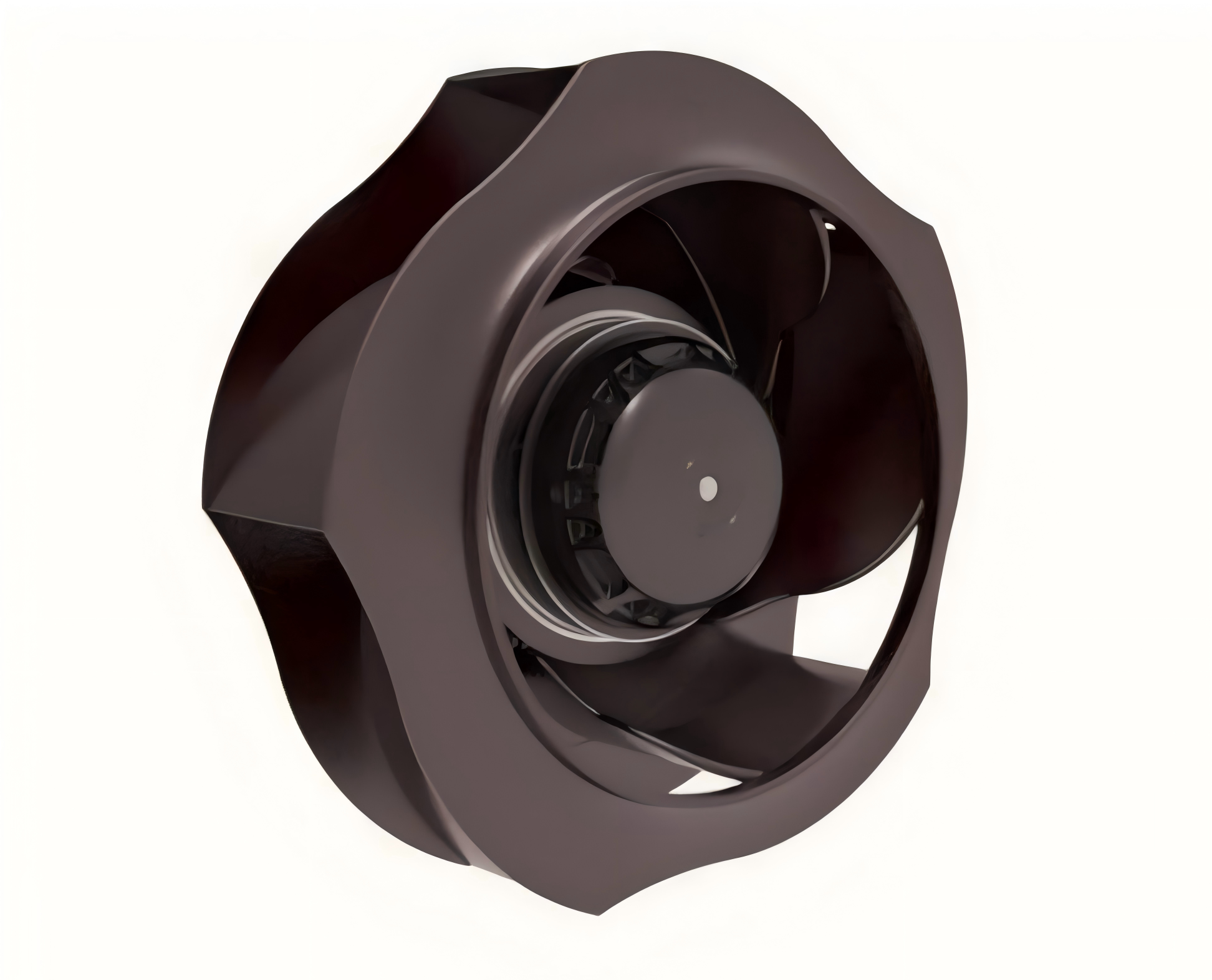
Backward-curved or inclined blades tilt away from the direction of rotation. They provide the highest energy efficiency for medium-to-high flow industrial applications. Engineers frequently use them in massive Air Handling Units (AHUs). They often operate without a traditional housing, functioning as plug-and-play modules. Their unique aerodynamic design makes them less susceptible to dangerous motor overload.
Straight radial blades extend straight out from the central hub. They are specifically built for heavy particulate loads, industrial dust collection, and pneumatic conveying. They rank as the least efficient and loudest options available. However, they offer unparalleled self-cleaning capabilities. They fiercely resist solid material buildup, making them indestructible in dirty environments.
Below is a summary chart comparing the three primary impeller designs:
Impeller Type | Ideal Environment | Efficiency Level | Key Characteristic |
|---|---|---|---|
Forward-Curved | Clean air, compact spaces | Moderate | Low speed, small footprint, sensitive to dust |
Backward-Curved | Clean to light dust, industrial flow | Very High | Non-overloading curve, highest energy savings |
Straight Radial | Heavy dust, material handling | Low | Self-cleaning, highly resistant to solid buildup |
You must evaluate several critical technical variables before finalizing an installation. Air movement calculations require precise mathematical alignment. A poorly specified unit will fail prematurely or waste massive amounts of electricity.
Volume (CFM) vs. Static Pressure: You must always plot the system resistance curve against the fan performance curve. The exact intersection forms your operating point. Choosing the wrong operating point pushes the unit into a "stall" or "surge" region. This instability destroys bearings and ductwork rapidly.
Drive Mechanisms (Direct vs. Belt): You must choose how power reaches the impeller.
Direct Drive: The impeller mounts directly onto the motor shaft. It requires lower maintenance and suffers zero transmission loss. We recommend it for continuous heavy load applications.
Belt Drive: A belt connects the motor pulley to the fan sheave. It allows easier speed adjustment via simple pulley changes. It also provides better shock absorption. It proves highly useful when you require specific RPMs outside standard motor speeds.
Flow Control and Energy Efficiency: Evaluate your control mechanisms carefully. Variable Frequency Drives (VFDs) drastically reduce energy consumption compared to mechanical dampers. Dampers waste energy by artificially choking the airflow. Airflow monitoring also differs by impeller type. You monitor forward-curved units using motor current. You must monitor backward-curved units using nozzle differential pressure.
Footprint and Housing Clearances: Physical constraints heavily influence design choices. The volute casing design mimics an ammonite shell. This expanding scroll shape significantly reduces fluid turbulence. Optimal impeller-to-housing clearances guarantee peak pressure generation. A standard rule maintains a clearance gap of roughly 0.25% of the impeller diameter.
Here is a quick reference table regarding drive mechanisms:
Drive Mechanism | Speed Adjustment | Maintenance Need | Best Application |
|---|---|---|---|
Direct Drive | Fixed (unless using VFD) | Very Low | Continuous duty, fixed volume systems |
Belt Drive | Flexible (via pulley changes) | Moderate (belt tension/wear) | Custom RPM targets, shock-prone environments |
Field engineering involves navigating hidden operational risks. You must prepare your installation teams for common mechanical pitfalls. Many excellent designs fail due to simple installation errors or environmental oversights.
The miswiring trap plagues inexperienced technicians constantly. Reverse rotation occurs frequently when wiring three-phase motors. If a centrifugal unit is wired backwards, it presents a confusing symptom. It will actually still blow air in the correct direction. However, it will operate at a severely reduced capacity and pressure. This anomaly makes diagnosis incredibly difficult. The system appears to work, but facility temperatures slowly rise, or particulate settles in the ductwork.
Acoustic challenges require proactive mitigation. High-pressure air movement generates inherent fluid turbulence, creating substantial noise. We must utilize modern mitigation strategies to protect worker hearing. Manufacturers employ aerodynamic housings to smooth airflow. They utilize advanced blade slotting techniques. Biomimetic trailing edges, such as serrated owl-wing designs, dramatically reduce noise profiles. They achieve this acoustic reduction without sacrificing critical static pressure.
You must carefully avoid aerodynamic stall conditions. Restricting airflow too heavily creates a dangerous operational state. If the system static pressure suddenly exceeds the unit's dynamic pressure capabilities, severe issues arise. The air can completely stop flowing. Sometimes it aggressively backflows toward the inlet. This fluid chaos causes severe mechanical vibrations. It strains the motor, damages bearings, and tears ductwork apart.
Conclusion
Choosing proper ventilation equipment is never a generic purchase. It represents a precise engineering exercise. You must actively match your facility's specific system resistance to the correct blade geometry and motor capacity. Always start by mapping your exact CFM requirements against your calculated static pressure. Next, assess your environmental air quality, noting particulate density and extreme temperatures. Finally, consult directly with your manufacturer to accurately plot your specific performance curve. This diligent approach guarantees long-term operational stability and protects your infrastructure.
A: Yes, provided the system utilizes a straight radial impeller designed specifically for harsh environments. This blade geometry prevents heavy particulate accumulation. Engineers often pair these radial units with robust industrial filtration systems for safe dust collection.
A: Axial fans pull and push air parallel to the rotating shaft. They excel in high-volume, low-pressure applications like open room cooling. Centrifugal units pull air into the center and push it out perpendicularly. They utilize rotational force to generate high pressure for restricted pathways.
A: They operate highly efficiently when you correctly match them to your system curve. Backward-curved impellers offer industry-leading static efficiency ratings up to 84%. Pairing these specific impellers with electronically commutated (EC) motors or Variable Frequency Drives (VFDs) maximizes energy savings.


